Smartphone controlled dirtdog (Roomba)
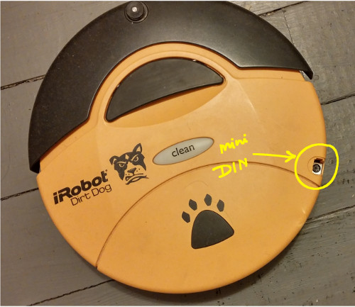
The iRobot DirtDog's (model: 110, Roomba) behaviour can be changed and full control over the hardware can be gained through the Serial Command Interface (SCI). The SCI uses a mini DIN connector to interface to the internal hardware. Details of the connection, port settings, modes and commands are given in the
Roomba SCI Specification document.
Arduino UNO microcontroller was used to send the SCI commands to the DirtDog. To get full control of Roomba's hardware a specific sequence of commands has to be send immediately after the power up. The first step is to wake up the device by setting the device detect pin low for 500ms. Once the device wakes up, a 'Start' command is sent to start the SCI interface. The next command immediately following Start is the 'Control' command which enables user control of Roomba. Finally a 'Full' command enables the unrestricted control of Roomba through SCI and turns off the safety features.
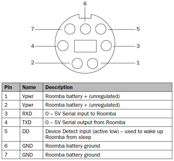
Figure 1 shows the schematic of the circuit used to control the Roomba. Figure 2 shows Roomba's serial port mini-DIN connector, which can be accessed from the top of the unit and is located on the edge, and their function. The power pin is directly connected to Roomba's battery, so at full charge it has a value of around 16V. This is also used to power the external electronic devices. Hence the voltage is regulated to 5V using LM309H regulator. The output of the regulator is connected to Vin and GND pins on the Arduino board for power.
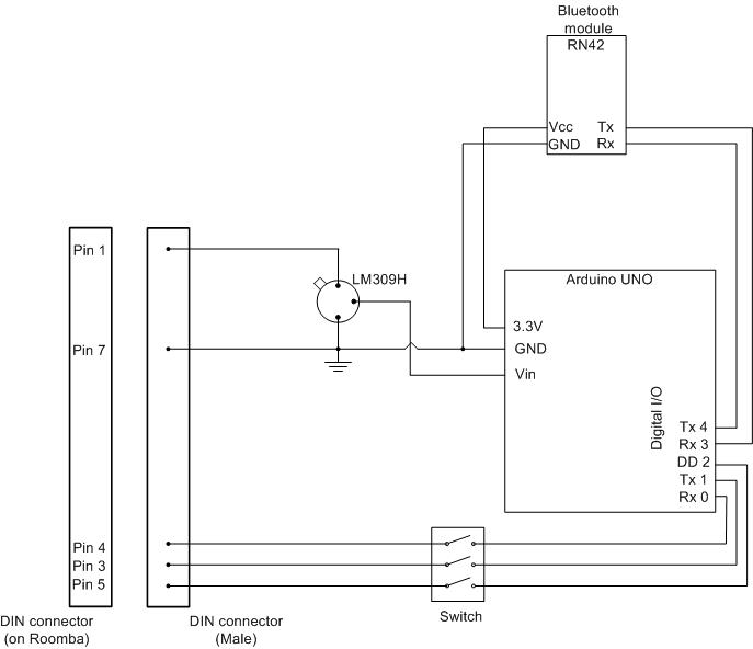 Figure 1: The schematic.
Link to the arduino sketch is given at the bottom of the page. The digital I/O pins 0 and 1 (Rx, Tx) on the Arduino are used for communication with Roomba. These pins are also connected to the Rx and Tx pins of the ATmega8U2 USB-to-TTL serial chip. So if digital I/O pins 0 and 1 are connected to the Tx and Rx pins of Roomba while programming the Arduino board, the Arduino IDE generates an error message and the program will not download on to the board. Hence, three dip switches are connected between digital I/O pins 0, 1, 2 of Arduino and Tx, Rx and Device Detect pins of Roomba. A switch for the Device Detect pin is not necessary but I happen to add one to it as well. These switches should be off while downloading the program to Arduino board. After a successful download, they should be switched on.
Figure 2(a) shows the mini-DIN connector on the Roomba and 2(b) shows the function of each pins.
(a)
(b)
Figure 2: mini-DIN connector and its pin layout.
The Roomba is remotely controlled via an Android device over bluetooth radio.
RN-42 bluetooth module was used on the Roomba for communication. The connectors on this chip do not have standard spacing. So the regular header pins will not fit in. But it is not that difficult to solder some 30AWG wires and make a simple breakout board. This chip costs ~$16 compared to the BlueSMiRF which costs ~$40. This chip requires 3.3V to operate so the 3.3V output pin on the Arduino is used to power it. The hardware serial pins on the Arduino (pin0-RX, pin1-Tx) are used for communication with Roomba. Hence a software serial port was used for communication between Arduino and RN-42 (Figure 1). For both RN-42 and Roomba, remember to connect the Rx pin to the Tx pin on Arduino and Tx pin to the Rx pin on the Arduino. The final hardware setup looks like as shown in Figure 3.
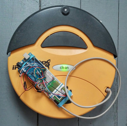 Figure 3: mini-DIN connector and its pin layout.
Once all the connections are made, download the Roomba.ino sketch on to the Arduino. Download and install Roomba remote control app on the Android device. As soon as the mini-DIN connector is pluged in to the Roomba, Arduino powers up and wakes up the Roomba. At this point, enable the Bluetooth radio on the Android device and pair with the RN-42 module. The RN-42 moduel shows up something like "FireFly-XXXX" and the default password is '1234'. After the bluetooth pairing is complete, open the Android app. The layout of the interface is shown in Figure 4 below.
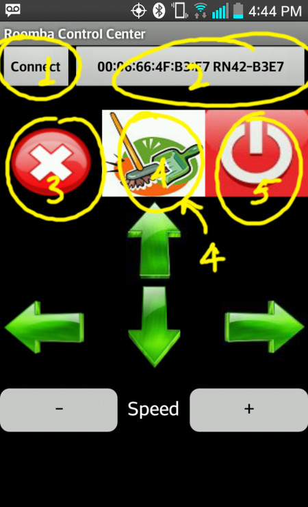 Figure 4: Layout of the Android app interface.
Click on the area marked as '2' in the figure to choose the bluetooth device and then click 'Connect' (marked as '1') to connect to the device. Once the Roomba is connected, use the arrow buttons to navigate. The button marked '3' is to stop the Roomba and the cleaning motors. When the Roomba starts the cleaning motors are not active. Clicking the button marked '4' in the figure activates the cleaning motors. By using the arrow buttons you can now move the Roomba aroud while it is cleaning. Clicking the power button (marked '5') shuts off the Roomba. Once the Roomba shuts off, you will have to press the reset button on the Arduino to reactivate it. This is still a work under progress and I plan to add some more sensors to the unit to make it efficient and autonomous. The speed function is also not yet been implemented on the Arduino.
Resources:
Arduino code:
Roomba.ino
Android app:
Roomba remote control
Test video:
Roomba test